
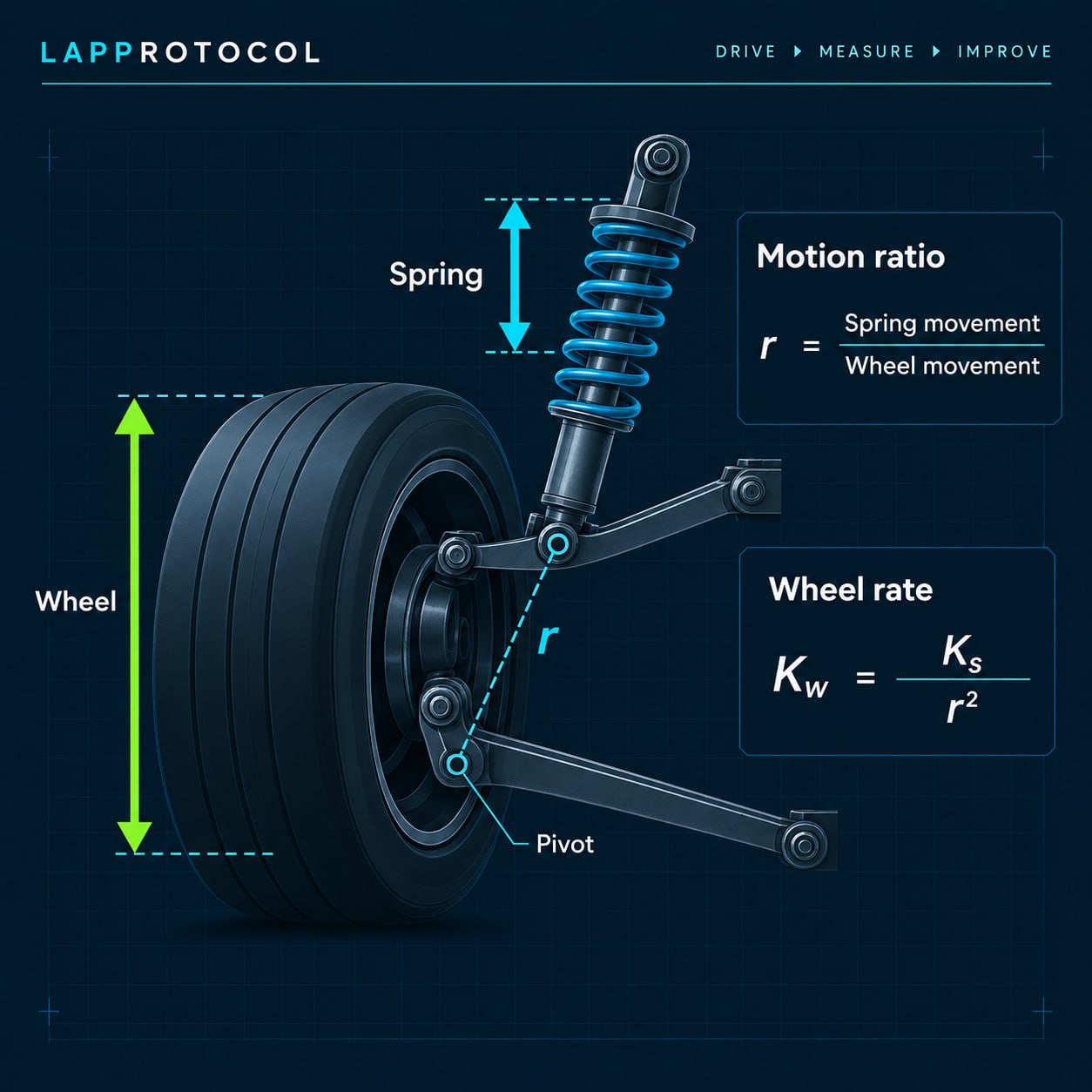
A spring’s quoted rate describes the spring itself. It does not automatically describe the rate that the tyre sees as the wheel moves. The spring may move a different distance from the wheel, and the suspension’s leverage changes both the displacement relationship and the force relationship.
That is why spring rate alone does not tell the whole story. To calculate a useful ideal spring contribution at the wheel, you need the spring rate, a clearly defined motion-ratio convention, and a consistent unit system. If the convention is reversed, the operation on the squared ratio is reversed too.
This article establishes the convention and formula that a future LapProtocol wheel-rate calculator can use. It does not build that calculator or recommend a rate for any vehicle.
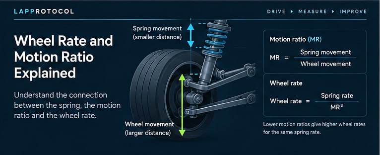
Spring rate is not necessarily wheel rate
Spring rate is stiffness expressed at the spring. In a linear example, a spring rated at 60 N/mm requires 60 N of additional spring force for each additional millimetre of spring compression. The quoted rate may instead be given in lb/in or another unit, but the unit is part of the value.
Wheel rate is the spring contribution expressed at the wheel. It answers a narrower question: for the suspension relationship being analysed, how much additional wheel force is associated with one additional millimetre of wheel displacement? It is not automatically the total vertical stiffness of the corner.
The difference appears because the wheel and spring may not travel together. A control arm, rocker, pushrod or other arrangement can make the spring travel less or more than the wheel over the same movement. The relationship may also change as the suspension moves.
Start with spring rate and units
Write the quoted spring rate with its unit before doing anything else. For the worked example below, the spring rate is 60 N/mm. If a source or spring catalogue gives lb/in, either keep the whole calculation in lb/in or convert the spring rate before combining it with other units. Do not mix N/mm with a displacement written in inches and assume the result remains meaningful.
A linear spring rate is a local or idealised description when the spring is being used over a range where its stiffness is treated as constant. Helper springs, tender springs, bump stops and other elements can change the effective response when they engage. Those are separate questions from the basic wheel-rate calculation.
Define motion ratio before doing any maths
Motion ratio is not a complete term until its convention is named. Two conventions are common and they are reciprocals.
Wheel-to-spring convention:
r_ws = wheel displacement / spring displacement
If the wheel moves 2 mm while the spring moves 1 mm, r_ws = 2.0. This is the convention written as wheel/spring travel in the OptimumG Springs and Dampers technical paper.
Spring-to-wheel convention:
r_sw = spring displacement / wheel displacement
For the same measured movement, the value is r_sw = 0.5. The relationship is reciprocal:
r_sw = 1 / r_ws
Neither convention is inherently wrong. The error is using one convention’s value with the other convention’s formula. A future calculator should therefore ask for the convention as well as the ratio, and display both beside the result.
Why the ratio is squared
The square is not an arbitrary correction. It appears because the suspension relationship changes both displacement and force.
Use r_ws = wheel displacement / spring displacement. If the wheel moves by W, the spring moves by S = W / r_ws. A spring with rate K_s produces spring force F_s = K_s S. For an ideal, frictionless mechanical relationship, virtual work is conserved over the small movement:
F_w W = F_s S
Therefore the wheel force is F_w = F_s (S / W). Substituting the spring displacement and spring force gives:
F_w = K_s (W / r_ws) (1 / r_ws)
So the ideal spring wheel rate is:
K_w = F_w / W = K_s / r_ws²
With the reciprocal spring-to-wheel convention, r_sw = S / W, the same result is written:
K_w = K_s r_sw²
The two formulas describe the same mechanical relationship. A wheel-to-spring ratio greater than one reduces the spring contribution at the wheel by the square of that ratio. Its reciprocal is less than one, so multiplication by the square produces the same result.
Calculate wheel rate
The calculation is short once the convention is fixed:
- wheel-to-spring input:
K_w = K_s / r_ws² - spring-to-wheel input:
K_w = K_s r_sw²
The result has the same force-per-length unit as the spring rate. If K_s is in N/mm, K_w is in N/mm. The ratio has no unit, but its convention must remain visible.
Do not substitute wheel travel for spring travel in the ratio, then apply an additional geometry correction without checking what the original measurement already contains. A ratio obtained directly from corresponding wheel and spring displacement already describes that measured mechanical relationship.
Worked teaching example
Representative teaching calculation - not a vehicle setup recommendation.
Suppose a linear spring is rated at K_s = 60 N/mm. During a small controlled movement, the wheel moves 2 mm and the spring moves 1 mm.
Using the wheel-to-spring convention:
r_ws = wheel displacement / spring displacement
r_ws = 2 mm / 1 mm = 2.0
Now calculate:
K_w = K_s / r_ws²
K_w = 60 N/mm / 2.0²
K_w = 60 / 4 = 15 N/mm
The ideal spring contribution at the wheel is therefore 15 N/mm for this defined relationship and position.
The same movement expressed using the reciprocal convention is:
r_sw = spring displacement / wheel displacement
r_sw = 1 mm / 2 mm = 0.5
Using the reciprocal formula:
K_w = K_s r_sw²
K_w = 60 N/mm x 0.5² = 60 x 0.25 = 15 N/mm
The result agrees because the convention and formula agree. The example does not say that a 60 N/mm spring or a 15 N/mm wheel rate is suitable for any real car.
The reciprocal-convention trap
The wrong calculation would take the wheel-to-spring value 2.0 and multiply by its square:
60 N/mm x 2.0² = 240 N/mm
That is four times the correct result for this example. Alternatively, taking the spring-to-wheel value 0.5 and dividing by its square also produces the wrong result:
60 N/mm / 0.5² = 240 N/mm
These are not competing engineering conclusions. They are convention errors. Before publishing an equation or entering a value into a future calculator, write the ratio as a fraction with words, then check whether the formula uses division or multiplication.
How motion ratio can be measured
The owner-driver concept is simple: measure corresponding displacements over a defined small movement. If the wheel moves 2 mm and the spring or damper moves 1 mm, the wheel-to-spring ratio is 2.0 and the spring-to-wheel ratio is 0.5.
A practical record should state:
- what point on the wheel or hub represented wheel displacement
- what point represented spring or damper displacement
- the starting suspension position
- the direction and size of movement
- the convention used in the resulting ratio
- whether the measurement was repeated
If the spring or damper must be removed, or if the car must be lifted, supported or partially disassembled, defer to competent mechanical practice and the relevant vehicle and component guidance. Never work beneath an unsupported vehicle. The article provides a measurement concept, not a lifting or spring-removal procedure.
Why motion ratio can change through travel
A suspension geometry is not necessarily linear. The relationship between wheel and spring or damper displacement can change through bump and droop. Body roll can also change the position and effective relationship on the loaded and unloaded sides.
That means one measured ratio may describe one position or provide a useful approximation over a limited range. It should not automatically be treated as a constant for the entire suspension. A future calculator should make the measurement position visible, and a more detailed model may need a ratio curve rather than one number.
A ratio measured directly from wheel and spring displacement already includes the installation geometry present during that measurement. If the geometry is analysed from drawings or separate component dimensions, the definitions must be made equally explicit. Do not combine a direct displacement ratio with another unexamined angle correction and count the same geometry twice.
Installation angle and double-counting geometry
An angled spring or damper can prompt a second calculation, but whether one is needed depends on how the ratio was defined. If actual wheel displacement and actual spring or damper displacement were measured directly, the resulting ratio already reflects the installation angle and leverage in that position.
Applying an extra cosine correction to that measured ratio can therefore double-count geometry. A separate angle treatment may be appropriate when starting from a different abstraction, such as a component length or a force projection, but the measurement definition must show why it is needed. This article does not prescribe a separate angle formula because the same angle can be represented differently in different models.
What wheel rate does and does not tell you
Calculated spring wheel rate is useful as an intermediate quantity. It lets you express the ideal spring contribution at the wheel and compare calculations made with clearly recorded assumptions. It does not establish total corner stiffness or a universal setup choice.
Other influences can contribute to what the tyre experiences, including tyre vertical stiffness, anti-roll-bar contribution during roll, bump stops or helper and tender springs when engaged, suspension friction and compliance, and nonlinear geometry. The presence and importance of each influence depend on the vehicle and operating condition.
Higher wheel rate is not automatically better. A calculated front/rear wheel-rate percentage does not universally determine balance, and no single spring rate follows from this article for a particular car. The calculation should support a controlled engineering question, not replace vehicle-specific evidence, component guidance or driver feedback.
The corner-entry understeer diagnostic method is a useful related reminder: a handling symptom should be separated from its possible causes before a setup change is made.
Practical checklist
Before calculating:
- State the spring rate and force-per-length unit.
- Measure or define wheel and spring or damper displacement.
- Write the motion-ratio convention in full.
- Confirm that the movements refer to the same position and direction.
During calculation:
- Use
K_w = K_s / r_ws²for wheel-to-spring. - Use
K_w = K_s x r_sw²for spring-to-wheel. - Keep the force and length units consistent.
- Check the result using the reciprocal convention if possible.
- Record the measurement position and assumptions.
Before interpreting:
- Do not apply a second angle correction to a direct displacement measurement without a defined reason.
- Consider whether the ratio changes through bump, droop or roll.
- Distinguish spring wheel rate from total corner stiffness.
- Do not turn the example into a vehicle setup recommendation.
Sources and methodology
The OptimumG technical paper is used for the documented wheel/spring travel convention and the squared relationship in its spring-rate calculation. This article’s reciprocal notation, measurement-record structure, double-counting boundary and interpretation limits are LapProtocol editorial methodology. The article is documentation-based and does not claim hands-on vehicle testing.
The formula decision for a future LapProtocol calculator is deliberate: accept either wheel-to-spring or spring-to-wheel, require the convention to be stored with the ratio, and apply division or multiplication by the squared value accordingly. A future calculator should also expose units, measurement position and limitations rather than presenting an unlabeled number.
Boundary: Wheel rate describes the ideal spring contribution at the wheel for a stated relationship. It is not a universal target, a complete corner-stiffness model or a substitute for safe inspection and competent suspension work.